Abstract : Details about the assembling of the definitive modular coils for UST_1 are reported. The materials, tools, time of operations and difficulties are briefly described. Some of the challenges are the tricky access and vision of the internal part of the grooves, the tendency to unwind and the non-perfect circularity of the conductors.
The modular coils for UST_1 were defined in February 2006. They are formed by 6 turns of sleeved flexible copper conductor made in-site. The section is 6mm2. Heatshrink tube was chosen as the adequate sleeve. Each conductor lasts 30 min to be assembled (unsleeve the original cable, sleeve again and 5 minutes of thermal treatment)
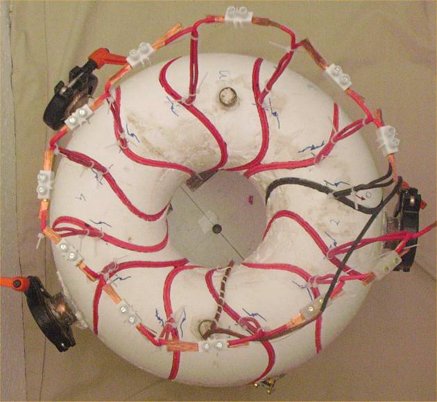
In July 2006 the coils are finally wound. The result can be seen in Photo 1.
In general the process has resulted as expected from the test coils made in February and in May. The coil tested in May was identical to the present coils and the test conductor is the one in black in the photo (it was unwind and rewind)
The winding of the non planar coils is very challenging because the conductor cannot be pulled to be adjust in the groove and sometimes the conductor is loosen when pulling (depending on the position of the conductor with respect the curvature of the groove). The compression against the walls of the groove is one solution to maintain the conductor in the correct position while winding. Additionally the vision of the internal part of the groove is sometimes not easy.
Process
Initially a 45º bend is produced to obtain a crossover as can be seen in Photo 2.
An auxiliary flexible and compressible thread of diameter slightly (0.4mm) bigger than the conductor is used as a pressure tool and temporal fixing of the conductor. See Photo 3. Two repetitive steps are followed:
a) First the auxiliary (in black in
Photo 2 and 3) and the real
conductor (in red) are wound simultaneously one turn.
b) Later the auxiliary thread is removed slowly and the
other segment of the conductor is located and compressed in the space,
forming the second part of the pancake. The process is shown in Photo 4.
The groove was designed and machined to achieve some level of compression, otherwise this particular winding would have been impossible. Two specific tools are used to press the conductors. The process is repeated 6 times per coil and lasts about 45min per coil. Adding 15 minutes to cut, adjust and connect the coils the average is 1h hour per coil. More time will increase the precision in some degree.
Finally the coils are connected by means of leadings adapted to the necessity of very low resistance. One condition is the possibility of disconnection and connection in series/parallel. The conductors might be soldered in a future. A splice similar to the ones applied to superconductors but without silver soldering is used. A brass rod with half circle cross section is utilized to compress one cable against the other along 2cm inside the leading. It is displayed in Photo 5
Difficulties
* Two suppliers of heatshrink tube are used due to holidays at one supplier. However one of the tubes happend to be more adequate than the other. The worst tube tend to poorly compress the filaments of the conductor and tend to adquire non-circular more irregular cross section which difficults the winding. The errors using this tube are about 50% higher than the best one.
* Each winding is a
double pancake. The external crossover compensates only partially the internal crossover
but it could be improved. The best solution by now is shown in Photo 6.
Additionally the successive coils are wound in a symmetrical manner
but only 12 coils compose the stellarator and 4 pairs
of coils have the upper terminals at long distance so compensation is poor. Some
improvements might be tested if magnetic
surfaces appear. The use of more turns would be the best solution but the
voltage and power supplies become far more complex (impossible 12V batteries).
Pairs of pancakes would be perfect but twice as grooves are necessary
following the present philosophy.
* The vision of the groove and conductor is sometimes impossible. Occasionally a mirror is used to help. The lower part of the torus and the first layer corresponding to the bottom of the groove are especially adverse. The torus is on the columns of the mechanising device but this legs are too short for the present function.
* The precision of the winding is lower than the precision of the grooves because the conductors tend to uncompress. Compressing beams might be used to maintain the external turns correctly fixed under any circumstance. However the supports or threads to fix these bemas are not prepared. The present prescision, without external pressure beams, is about +-0.3mm.
References
None
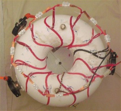
Photo 1 . Top view of UST_1. 12 definitive modular coils formed by 6 turns in a precision groove. The winding is made by a double pancake, 6x2 turns.
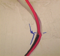
Photo 2 . Internal crossover. Pressure thread to maintain the coil in position while winding (in black). The internal crossover is compensated by a symetrical external crossover.
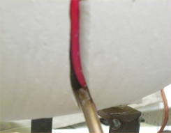
Photo 3 . Both cables (real and auxiliary) are compressed in the bottom of the groove and against the lateral walls.
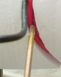
Photo 4 . The other part of the conductor is located in the space left by the auxiliary coil. The thin tool is usually used.
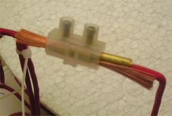
Photo 5 . Splice of conductors mutually compressed by means of a special brass rod.
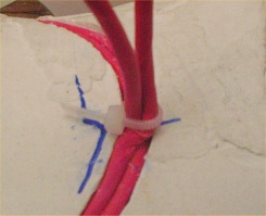
Photo 6 . External crossover. The compensation is not perfect becasue it is 6mm over the internal crossover and because the bends are complex to accurately mechanise and locate.
Date of publication 29-07-2006