Abstract : The planned system, calculations and initial tests of the ECRH heating system for UST_1 is described. It is based on a commercial magnetron at first or second harmonic at 2.45GHz. The lines, matching device and antenna are simulated by the free LTSpice code. Dozens of real experiments are carried out out to test the lines, connectors and the transmitted power in a pulsed regime of ~0.6kW. The lines only withstand 100W in CW duty. Almost 150W are supplied to the calorimeter for 6 seconds. RF measuring instruments (a directional coupler and detectors) are being shipped to measure the efficiency and the elements with excessive VSWR.
Previous calculations
Some previous general calculations were
accomplished in "Heating
system in UST_1".
Other calculations related to heating in UST_1 can be found in "Energy
confinement time and estimation of the heating system in UST_1" in
this web site.
The main points in those
publications are:
* Max. plasma temperature : UST_1 could reach 2eV if 1Kw of heating power is used asuming 30% of power absorbed.
* High density cut-off for X-mode is possible from 1.15 to 1.5 x 10⁻¹⁷ m-3 for the possible B [0.043 , 0.087] T . At ~10-18 m-3 the plasma will be heated by multiple reflections between the cut-off layer and the vessel walls resulting in a hollow profile of temperature.
* No Mode Conversion is supposed.
* The antenna will be a stub 1/4 * wavelength * factors = ~3cm. Waveguides are impossible in UST_1 at 2.45GHz
Specifications of RF cables
and connectors
Type N connector and cable style RG214 (similar to RG9) are common cables and connectors. They withstand far less than 800W in CW duty.
The suitable choice for continuous duty would be the connector 7/16 and cable LMR900 or superior. These components are expensive and difficult to find in ebay so overloaded elements are chosen for pulsed work.
Cable : The specifications for RG214 from different sources of data and for CW are (kW) : 0.16 , 0.11 , <0.3 , < 0.2 at 2.45Ghz . Suppose 100W for continuous duty. The pulse lasts 2 seconds max. About twice the CW power is stated in one data source for 50% duty. Peak power (only microseconds) is more than 1000 kW from another source. So 0.5Kw or 1Kw will be possible under pulsed duty (2 seconds ON, 5 minutes OFF). Power loss is : 13.7dB/100feet , 12.4dB/100feet at 2.45GHz so consider 14dB/100 feet. It is no relevant for a cable of 2 feet length.
Connector : 300W for 1GHz and CW. Can be estimated as 100W CW at 2.45GHz. Similar reasoning for pulsed duty.
RF system in UST_1
Elements :
* Generator. One commercial microwave oven ~0.8kW CW. Two microwaves could be considered.
* Waveguide to coax adapter to pass the microwaves to a coaxial cable. It has been built in site and it works aceptably well.
* Transmission lines able for ~0.8kW at 2.45GHz . Waveguides would be better but the ports of UST_1 are to small for 2.45GHz. They are composed by pieces of RG214 cable with N Type connectors. They were purchased time ago and some new shorter pieces will be ordered soon.
* Dual directional coupler to measure the reflected power and maximise the forward power during tuning. Two unused NARDA dual directional couplers, 45dB directionality, 30dB pick off, 250W CW, N connectors, are being shipped from ebay.
* Two Biased schottky diode detectors to measure the forward and refleted power. They have been found at low cost and will be purchased soon. The brochure from 'Agilent' specifies the features. Other information is available in [3] Chapter 11 and others.
* Several attenuators to lower the RF signal to the requirements of the detectors. Power = 1W is enough.
* Several terminations-dummy loads to close unused SMA connectors of the directional coupler. Power = 1W is enough.
* Two multimeters to measure the signal from the detectors.
* A Double Stub Microwave Tuner. This component, for 2.45GHZ and ~250W CW, is difficult to find or it is expensive if new. Perhaps it can be built in site. It will be regulated according to the calculator in [1]. Other expressions appear in [2] 2.5.2 for a single-stub tuner.
* RF feedthrough, Type N, made in site. The design is based on a NW40 flange and a Bulkhead Adapter Type N. A provisional feedthrough has been built. Hositrad sells commercial items although too expensive.
* Short final RF transmission line along the VV port and stub antenna. The spreadsheet to calculate characteristic impedance, capacitance, inductance, radiation resistance, input impedance, and bandwidth is working. Many expressions come from [4]. The spreadsheet is tested with some examples in [4].
* Microwave leak detector to detect any leak.
"Engineers' handbook of industrial microwave heating" [5] is a very informative book for the design of heating systems.
Simulation of the behaviour of the system.
Plasma coupling
The free version LTSpice from Linear Technology is used to simulate the RF system, shown in Fig 1.
The result of the tuning of the system with a Single quarter-wave section of transmission line, [4] , is shown in Fig. 2 . The system is matched, for R antenna = 10 Ohm. Only the real part can be match with this tuner. The double stub will be also simulated.
Plasma behaviour is unknown and it is seems very different from one condition to another. "The coupling of electromagnetic power to plasmas" [6] might be useful. One reference cites a value of resistance between 1 and 10 ohms and a reactance between 0 to 150 ohms in a capacitively coupled plasma. Some possible working points are calculated, [1], and it seems that the double stub tuner will be able to match any combination of R and X. Plasma impedance is not further studied now due to the difficulty of the issue. Furthermore the tuner will need a trial and error regulation even if plasma impedance calculations are carried out.
Tests and experiences
Tests of RF cables and connectors
Cable : The junction of the cable with the N connector softened in a first test (the matching was clearly dreadful in this experience).
In the recent second test (new adapters, better matching) the cable withstood 6 seconds at about 300 - 500W. Therefore RG214 cable or similar is enough for pulses 2 seconds long.
Connector : The connector withstood medium power (about 200W) for 6 seconds in the first test . The dielectric partially melted after 30 seconds.
In the recent test the connector withstood around 200 - 400W for 6 seconds. The connector did not apreciable heat. It is enough for pulses 2 seconds long and besides it does not disagree with the specifications.
Experiences in the microwave (no lines)
8 pulses are produced with the calorimeter in the original microwave (no waveguides or lines). The heating time is between 5 and 6 seconds in every case. The calorimeter is located in different positions (height and surface). The average of the eight values is 54% efficiency and an average of 430W is transmitted to the load. The min. efficiency is 35% and the maximum 67%, depending on the height and the position. In general the central positions are the best in this microwave.
ECRH transmission test in a dummy volume
The experience-test expressed in Photo 1 is carried out.
Care is taken during the experiences because high voltage appear in the lines. Typically 224V for 1kW in a 50Ohm system. Votage peaks might appear, especially if metallic tips are present in the system. Also the microwave leak detector is continuously monitored to detect any small leak. The detector has been tested and it is sensible to very small signals. No leaks were produced during the experiences.
A waveguide to coax adapter made in site is placed in the microwave, Photo 2, very near the microwave waveguide. The connection should be electrically continuous but it is only a test and it will be well fitted in the future. The waveguide to coax adapter is made with a simple aluminium rectangular tube of 80 x 40 x 1.5 mm ext.
The waveguide wave length Lg, by chance is exactly 5.0 cm. A brass conical probe, 3cm length, is situated at that distance from the short.
The coaxial cable passes through the hole for the motor of the microwave.
The line is about 30cm length of RG9 cable.
The receptor, Photo 3, is a piece of the same aluminium tube of 10cm length with a cylindrical probe at 5cm from each side and an aluminium cap (not shown in the photo).
A simple calorimeter, formed by a plastic container filled with 20cm3 of water, is utilized to measure the power supplied to the load.
Pulses
3 pulses are produced in the system (adapter, line and receptor volume). The power received by the load is 150W , 117W , 139W. Average = 136W . It is only 32% of the total available power. It is not a bad result until the measuring elements arrive. 200W will be enough at the begining although 300W effective power were calculated and 400W gross power should be achieved.
Some previous experiences were carried out with a ferromagnetic waveguide to coax adapter having incorrect bottom short and the adapter not totally focused on the microwave waveguide. The result was extremely poor, only ~25W of output.
Experience to test the effect of the cable and connectors
2 pulses are produced with the addition of a RG214 cable of 1.8m length and the necessary male-male Type N connector. The results are 71.9W , 72.0W . Average 72W of received power. 47% of the power is lost. Attenuation of the line (1.8m of RG214) is 0.83dB so the power is 136/1.2 = 113W.
VSWR ratio for connectors is not exactly known. Some references state less than 1.3, others ~0.15dB. Taking WSVR = 1.2 and two new connectors in series then 0.91 * 0.91 * 113W = 93W. Perhaps considering insertion loss for the male and the female is correct and then 0.91^4 *113 = 77W not far from 72W.
In any case an order of magnitude of the losses has been calculated. The length of cable and the number of connectors must be minimised at this relatively high frequency.
Further developments
The remaining RF elements will be received and installed. First tests in UST_1 will be carried out before the measuring devices arrive. A first plasma will be tried before or after the whole RF system is completed.
References
[1] Double stub tuning http://www.ece.ndsu.nodak.edu/
%7Eronelson/mes/programs/dst.htm
[2] "Principles of RF and Microwave Measurements (Lecture Notes for ECEN 4634) ", Zoya Popovic and Edward F. Kuester
[3] "The ARRL UHF/Microwave. Experimenter's manual" American Radio Relay League.
[4] "Calculo de antenas" Armando García Dominguez. Marcombo Boixareu editores.
[5] "Engineers' handbook of industrial microwave heating" Roger Meredith , The Institution of Electrical Engineers.
[6] "The coupling of electromagnetic power to plasmas" , R. Koch , Transactions of fusion science and technology , vol 45 Mar 2004.
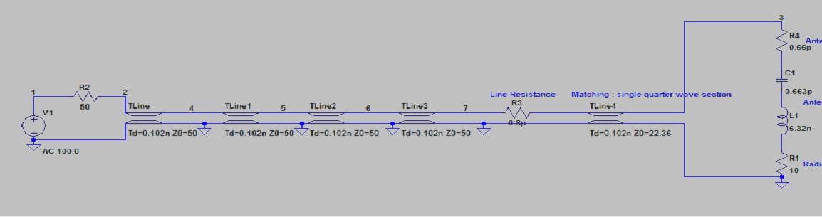
Fig 1 . Layout of the RF system. It simulates transmission lines, matching tuners and antennas. It is the layout from the free version of SPICE , LTSpice from Linear technology .
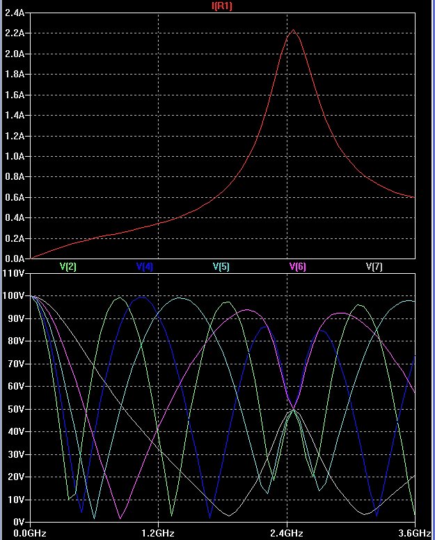
Fig 2 . Matching impedances after calculation of a Single quarter-wave section of transmission line. The matching is perfeact because the losses in the line and antenna are set to zero. Some other simulations are carried out with normal mismathes and imperfect lines and possible values of plasma-antenna impedance.
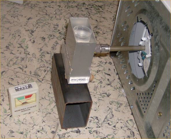
Photo 1 . Receptor (piece of aluminium tube), leak detector and coaxial line from the microwave generator. The calorimeter is inside the receptor. The receptor is closed with a fitted aluminium cap during the pulse (not shown).
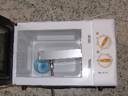
Photo 2 . Waveguide to coax adapter . It is not yet fitted to the microwave waveguide.
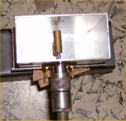
Photo 3 . Receptor opened and without the calorimeter. The cylindrical probe 3cm length is shown.
Date of publication 12-01-2007