Abstract : The calculation of the stress in a porcelain vacuum vessel for the UST torus is described. The only load considered in this calculation is the atmospheric pressure. Magnetic forces are very low if only a basic set of power supplies is used. The objective is to continue experimenting with the code_ASTER and to obtain an approximate value of the stress in the structure..
Modelling
The major radius of the torus is 0.1125 m . The
minor radius of the external surface of the torus is 0.04775 m and the
thickness of the wall is 10mm. The reason of the relatively thick wall is
the specific process of moulding that is foreseen and to allow attaching the
external flanges to the non-protuberant ports of the torus. A figure
representing the present idea about this type of ports is shown in Graph 2.
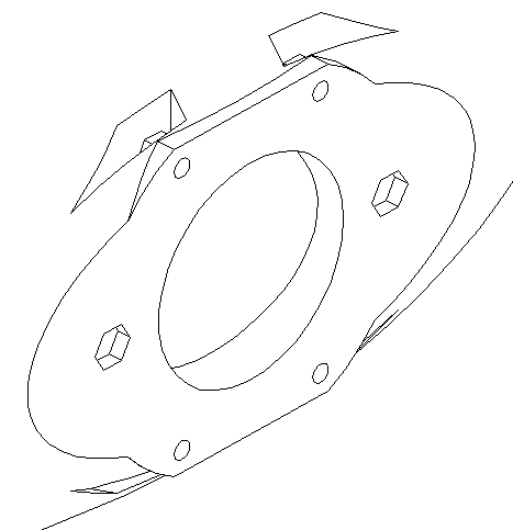
The model for the finite elements code, ASTER, has been simplified. Instead
of 5 ports like the one in Graph 2 only one was modelled. The structure of
the port was reduced to a square hole. See the design in Graph 1. The port
is at the bottom left of the figure.
The atmospheric pressure on the port section is applied on the
borders of the rectangular port. A pressure of 1 bar = 100000 N/m2
is applied on the rest of the external surface of the torus and
perpendicular to each element of the surface.
The electro-magnetic forces are small, about 4N/linear-cm of coil
if the current in the HF coil is 710A. See calculations in [1]. Therefore
these forces are not applied in the calculation.
Non-protuberant ports
The general structure of the
torus is thought to be similar to CTH, m=5 , l=2, [2] , but only 5
equatorial ports are planned.
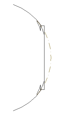
The ports are thought to be flat to allow changing the shape and
distribution of the windings on the surface of the torus. In Graph 3 a
profile of the port is displayed.
Dashed lines in Graph 3 represent the mathematical section of the
torus and continuous lines the contour of the port. Only two small parts at
the top and bottom of the port protrude a few millimetres. The necessity of
nuts to fix the port is the reason of this extensions. This configuration
forces the use of two stuck nuts.
The porcelain torus should be moulded by mean of a tapping process. As a
consequence the thickness of the wall remains constant even if 4 slits like
the ones in Graph 2 are planned for 4 nuts.
In this design part of the ports can be covered by coils in order
to admit future unknown configurations. The number of periods could even be
changed to l=3, l=4 or other. Moreover the TF coils for a classical
stellarator, style WEGA for example, will fit over the ports.
Solution using ASTER
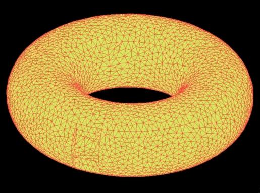
The general process of meshing with GMSH and solving with ASTER is described in [3]
The present model uses "3D modellisation" and the constraints are supposed to be on a ring on the internal hole of the torus.
The properties of the material are: Young’s modulus 137GPa ; Poisson’s ratio 0.19 corresponding to an average Zircon porcelain.
All this values were defined using EFICAS, a tool to easily define the FEA model in ASTER.
The distribution of Von Mises stress around the port is represented in Graph 4. The maximum value is 1.36 x 10⁶Pa and the minumum 1.1x10⁶Pa . Maximum values are around the port.
The stress, as was expected, is very small and far from the tensile strenght of an average zircon porcelain, about 700-1000 Kg/cm2 .
Further developments
If more power supplies were available the magnetic forces should be introduced in the model and the maximum current would be calculated.
References
[1] "Forces on HF coil of the first outline of the UST_I" . See "All past research" in this web.
[2] “Design and construction progress of the compact toroidal hybrid" Hartwell, G.J., Knowlton, S.F. Watts, C.Hanson, J.D., Brown, T.
[3] "FE stress analysis of the case for the TF coils in HT-7U using Code_ASTER and GMSH" . See "All past research" in this web.
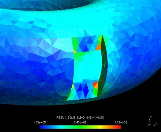
Graph 4 . Von Mises stress around the port
Graph 1 . Deformation of the TF coil under out-of-plane loads. Units in meters. Calculation using ASTER-GMSH
Graph 2 . Present ideas about a non-protuberant port.
Graph 3 . Distribution of Von Mises stress. Units in Pa. Calculation using ASTER-GMSH
Graph 4 . Von Mises stress around the port
Last Update 22-07-2005