Abstract : Analysis of the images from some field line mapping experiments and comparison with the theoretical simulations. The consequences of the results are very positive because they give a first positive support to the correction of UST_1 design and construction. It is only an initial positive sign that will be confirmed in next experiments.
General description
The field line mapping system for UST_1 was design some time ago and it is described in [1]
In essence it consist of :
a) An in-site made electron gun of small size (20mm length and 12mm diameter), ~0.5mA e-beam emission, formed by very low cost materials (about 3€).
b) An oscillating fluorescent rod of 1mm diameter that is driven by a removable external magnet. It oscillates freely during the pulse and the magnet is removed to a distant location during the pulse. The materials of this device cost ~0.3€.
An e-beam of ~2mm diameter (sometimes 3mm diameter) of enough power is produced to carry out some basic experiments even utilizing a very low cost e-gun. However the plasma size is very small, 40mm, so the beam diameter is excessive. It will be improved.
SimPIMF, described in other pages, is used to compare the experimental results and the simulated predictions.
No complete magnetic surfaces are observed in this series of experiences because the simulations show that the 4th turn of the e-beam collide with the rear of the e-gun. The reasons are : 1) the rotational transform, below 1/3, was designed to be quite flat to avoid rationals, but it is even flatter for high energy electrons (~50eV is high for UST_1) used for the field mapping. So the 4th turn collide with the rear of the e-gun for nearly all the magnetic surfaces. Only near the LCFS and in some few particular points the simulation reflects that the e-beam can pass near the lateral of the e-gun. An e-gun of smaller diameter will the solution.
2) Mean free path at this poor vacuum allow only less than 10 turns. Some calculations below.
It should be kept in mind:
* This is a very low cost stellarator and results cannot be as spectacular as in normal or expensive devices.
* A lot of effort and time has been utilized to design and built UST_1 stellarator. So,
- If the device do not show any behaviour as calculated and simulated perhaps SimPIMF code is mistakenly operating, or the coil mechanising device failed, or any step in the process was incorrect so the real coils would be erroneous and the notable effort would have been useless in some degree.
- If the device shows some predicted features, it is a great success, and some other difficult experiences can reasonably be simulated and predicted.
These first experiments seem to show that UST_1 has a correct behaviour and probably no important mistakes have occurred during the long process of design and construction.
A table with the whole series of pulses can be seen in [2]
Significative pulses are described below.
The camera was not moved from #126 to #142 and it was slightly moved in the next to have better field of vision.
The location of the e-gun emission point in the simulations is the same as the measured real position in all the pulses. The e-gun can only be moved around a far rotation point so the movement is almost vertical. As a result each series of pulses have the birth point of the beam on the same vertical (z coordinate in the simulation). Everything has been measured to know as better as possible the real location of the e-beam. However it seems that no more than +-1mm in vertical and +-0.5 in radial coordinate has been achieved.
Analysis of pulses #126 #127 #128
The pulses were done after 3 days of outgassing of the vacuum vessel. The pressure reached 6 x 10⁻³Pa.
* The mean free path of electrons in Nitrogen at 30eV is 6.9m . The value is obtained from the cross section of electrons in Nitrogen at this temperature obtained from [3]. For Maxwellian distributions Mean Free Path = 1(pi * cross section * densitiy) . It results 9 turns around the torus having the remaining beam a power 1/e intensity. So this level of vacuum is able to allow several turns of the e-beam.
* The position of the e-gun was not determined to obtain any particular result and the position of the e-gun was only roughly known at the moment of the experiences. The exact position was measured later by means of a particular measuring tool designed and built to measure the position of the e-gun.
* The theoretical trajectories are calculated using SimPIMF code. It has several types of simulation. Drifts orbits were not simulated to optimise the stellarator when UST_1 was designed. It was thought that the orbits were similar to the Poincare simulations (in the code "Poincare" are the simulations without drifts) and it is true at the low temperatures of the possible plasmas in UST_1 (< 5eV). However it was not realized that field line mapping is not normally possible at this low energies and that drifts are important at the designed magnetic field B (and more having 1/2 of the designed B like presently) . Large drifts in relation to the plasma size are negative for field line mapping but not for the normal operation of the device at lower energies.
* The images are the poloidal projection of the e-beam for each pulse. The vision system requires the overlapping of several frames for the same record. Each record lasts 2.5 seconds of useful information plus some start-up and and switch off time at 30 frames per second 640 x 480 pixels in colour. The images are overlapped by means of the arithmetic "maximum" of each frame and the accumulating image. They are not digitally filtered. An interference band pass optical filter around 505nm is used on the objective of the camera. The camera is tilted 15º with respect the poloidal projection plane so some deformation is produced in the recorded images. By now only an stretch of the image (only adequate at the right of the image but there is no image at the left) of 1.075 is produced to partially correct the calculated real deformations. A better solution, described in [1] is not used here
* Every resulting image, for example Photo 1, is located at the correct real position in the representation-simulation code. The simulated projection points appear on the image and the display image is copied by PrintKey screen saver code. The result appear in Photos 2 , 3, 4 and others.
The representation-simulation code can represent each projected point in different colours so as to know the order of the orbits and projections. First point in red, second in orange, third in yellow.... They turn always in counter clockwise sense and rotate less than 1/3 of 360º between points. It is correct for to the design Iota. Iota was designed to be near 1/3 at the centre and decreasing very slowly (flat profile) towards the LCFS. In field mapping at 50eV, high energy, drifts deform the correct profile and it seems that the profile is even flatter so it is similar to 1/3 in all the section. Drifts affect far less at 2 or 5eV, the max temperature in UST_1.
* The diameter of the e-beam is excessive but in other records, like in Photo 1, points are clearer and small. The first pulses give relatively clearer points than the last. The issue is very strange. Vacuun quality could influence in the 2nd 3rd .. but not very much in the first
Analysis of pulses #140 #138
This point belongs to the next series of pulses.
* The e-beam was positioned so as to try to obtain more than 3 points. An outer magnetic surface is chosen and a particular position. It has the 4th point at 10mm from he centre of the e-beam. The external radius of the present e-gun is 7mm so the 4th orbit should pass very near the e-gun, but do not collide.
* The experimental result and the theoretical points can be seen in photos 5 and 6. There is a deviation in these cases. A rotation error of about 10º is found in both images. Other later simulations are done in similar positions and they confirm the results from the pulses #134 to #142.
* The whole magnetic surface has not been obtained. A smaller e-gun could be the solution.
About the outward shift
* There is an outward shift of the experimental points with respect the simulated. In all pulses the points are 3-4mm to the right with respect the simulations. It seems the main reason for the deviation in pulses #138 and #140. In this case, and not in pulses #126 to #128, the e-gun is located radially-equatorially so the simulation cannot reproduce the real images. Some effort has been done to try to discover the reason of the outward shift:
- The minor radius of the winding surface is ~ 0.5mm higher in the real device than in the design. Simulation including this correction gave a slight improvement but no enough.
- A new module to calculate drifts has been developed. In this code the curvature of B is calculated at each point and part of the drift comes from this curvature. The result is practically the same as using the old code.
- The modification of the emission point in the simulation (in case the real measurement were inaccurate) gives an improvement in the rotation angle but the size gets worse.
- A change of 10% in the magnetic field is also of little importance.
- A change in the energy of electrons gives no concordance.
- Taken 20% of perpendicular velocity component to consider some lack of alignment of the e-gun gives no significant modification.
- The accuracy of the magnetic grid was doubled and the result was the same. The Step length was divided by three given the same results.
** The reason for the small deviation is unknown at the moment. It will be discovered some day.
Some other unknown facts
* It is not clear now why the diameter of the e-beam varies. The power supplies have small ripple. Usually the first pulses of the session give better points than the last. Heating of the coils or the e-beam?. Perhaps dispersion of energies in the e-beam? The distance from the filament to the acceleration hole should be changed to obtain better points.
* Some points are weak in one frame and recover the energy in others.
* An anomalous movement of the points around +-1mm is very probably produced by a lateral movement of the oscillating fluorescent rod.
Necessary improvements
A smaller e-gun should be built to obtain the whole magnetic surfaces.
References
[1] Design of the field line mapping system for UST_1" . Vicente M. Queral. See All past research
[2] "Pulses from #50. Towards the first plasma" Vicente M. Queral. See All past research
[3] http://ftp.fi.muni.cz/mount/muni.cz/physics/data/
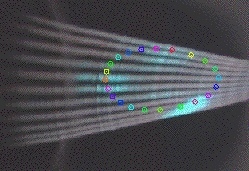
Image 7 . Pulse #126. The implicit simulated magnetic surface is represented. It cannot be recorded because the e-beam collides with the rear of the e-gun at the 4th turn.
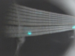
Photo 1 . Here two points are clear and well defined and the third (the superior central) is faint but appears repeatedly in different frames so it exists. The real image is 49mm width but the image needs a minor deformation due to perspective effect. Pulse #135.
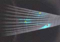
Photo 2 . Pulse #126 and simulated theoretical projections (in red, orange and yellow). The approximation is notable. The first projected point, in red, in the most intense cyan point.
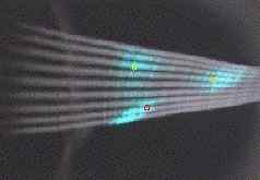
Photo 3 . Pulse #127
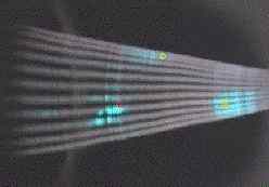
Photo 4 . Pulse #128
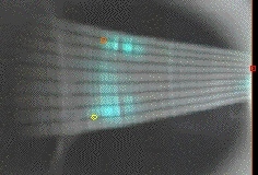
Photo 5 . Pulse #140. There is small deviation of 2mm from the experimental image to the simulated points. The difficulties to find the reason are explained in the text
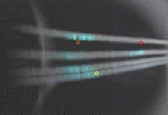
Photo 6 . Pulse #138. The same deviation as in pulse #140. A ~10º rotation is the observed deviation in all images of the second session of pulses (#138 , #140). The e-beam is located in a more delicate position.
Image 7
.
Pulse #126. The implicit simulated magnetic surface is represented. It
cannot be recorded because the e-beam collides with the rear of the e-gun at
the 4th turn.
Date of publication 07-08-2006.