Abstract : Abstract : The calculation of the forces on one possible helical coil of the torus is carried out. The torus is named UST_I . The objective is to roughly validate the idea of a porcelain torus capable of different configurations of coils and know if it could withstand the required magneto-mechanical loads.
New data about the design
Some of the ideas that appear in [1] have been changed to improve the design. Fist of all the size has been increased 1.5 times the previous one. The reason is to provide more space inside the torus for diagnostics, or for a possible future ECH system, a wide CCD window port or other elements. The cost of the coils is about 3.4 times higher. However, due to the low percentage of the total cost it is no excessive. The main increment of total cost comes from the extension of the power supplies.
The decision between torsatron or classical stellarator has been solved by means of a torus with non-protuberant ports that will allow to change the position and shape of the coils and even cover part of a port. The present ideas about this type of ports is displayed in Graph 1. Therefore the torus could employ classical stellarator coils, for example something like WEGA stellarator, or torsatron coils, that could be similar to CTH torsatron. It could be even thought that the device were a tokamak.
In a next future this ideas will be expressed more clearly in another page.
The name of the torus will be UST_1 that stands for “Ultra small torus”, model one.
The material of the vacuum vessel might be porcelain because it is easily conformed in complex shapes, ports can be reproduced in different units without difficulty, the material is cheap, it is non-conductor (no eddy currents), it is not magnetic if the purity of the raw materials is high and finally this region in Spain is the second world producer of ceramic tiles. Stainless steels seems to be more complex as a whole
Drawbacks of porcelain is the relatively low strength (mainly against tension), it is fragile, outgassing could be higher that the data presently available, excessive deformation when firing and risks from this unknown conception.
Modelling
The major radius of UST_1 is 0.1125 m . The minor radius of the external surface of the torus is 0.04775 m
A current of 500-700A seems achievable considering a first set of power supplies. Presently a number of four batteries of 45A-h 12V is considered. Some experiences are in process to refine this value.
A torsatron model is considered below. The size of the helical coil, HF, and poloidal coil, PF1, is a reduction of the ones in CTH [2] [3]. The pitch and shape is conserved. The calculation of a system of coils having good stability or equilibrium properties is not the objective here and moreover I do not have the knowledge nor the codes to do this.
The winding of the HF coil has 16 turns and the conductor 35mm2 section. This could be changed depending on the type and power of the power supplies.
Each PF1 coils has 16 turns and the section has not been calculated yet.
HF and PF1 currents are obtained using MEMCEIv2.1 [4] . The ratio between HF and PF1 currents is obtained when the integral of the vertical field along the axis of the torus is zero. Next, the two values of currents are scaled to obtain a reference value of average |B|=0.1T on the geometrical axis of the torus.
The result is
IHF = 710A ; 11360 A-Turn
IPF1 = 262.5A ; 4200 A-Turn
The module of B over the geometrical axis fluctuates from 0.094T to 0.112T in five periods.
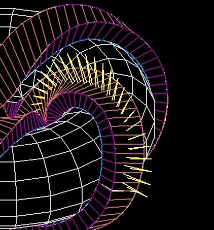
From MEMCEI the maximum module of the force is 4.14N on an finite element 8.26mm long, towards the exterior of the torus. The minimum force is 1.81 N on a finite element 9.2mm long. In this model the length of the elements varies due to the pitch function.
The forces are very small, but if the currents were 10 times higher that force would be 414N on one element.
The direction and magnitude of the forces is shown in Graph 2.
The vacuum vessel has to withstand these forces. In spite of this the forces will remain notably low, in the order of the atmospheric pressure, due to the high cost of the power supplies.
It is thought to create a porcelain torus with a notable accuracy over the exterior surface of the torus in order to use this surface as a geometrical reference to wind the coils.
At high currents, for example IHF=2900A , 50V , 1 second pulse, the temperature of the coils described above, considered adiabatic, will rise 35 ºC. We conclude that the rise of T is reasonable low if the pulses are of the order of 1s .
Further developments
The calculation of the thickness of the the vacuum vessel will be done using the last values. Because of the low forces, only a marginal attention is necessary.
References
[1] "First approaches for the design and construction of an ultra small torus to experiment with fusion technologies" , Vicente M. Queral . See “All past research”
[2] “Design and construction progress of the compact toroidal hybrid" Hartwell, G.J., Knowlton, S.F. Watts, C.Hanson, J.D., Brown, T.
[3] Private information from Hartwell, G.J. , Auburn University
[4] "Forces and momentum on TF coils of HT-7U. Calculation using MEMCEI v2.1 finite element code", Vicente M. Queral . See “All past research” . See other explanations about MEMCEI
Graph 2 . Magnetic field in the plane x=0 . Quadrant X+ Y+ .
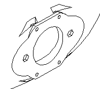
Graph 1 . Present ideas about a non-protuberant port.
Graph 2 . Forces on HF coils for this particular design of UST .
Last Update 21-07-2005