Abstract : To advance the test of the MEMCEI v2.1 code the calculation of the forces and momentum on the TF coils in HT-7U tokamak is carried out. In this case another a more recent report from HT-7U is used. The profile of the forces along the length of the coil is obtained and compared with the report from the HT-7U team.
Modelling
The system is modelled like shown in [5]. The report [2] from HT-7U team was used in a past study but in this study the report [1] is used. Report [1] is more recent and it has a more developed geometrical design. This design (not the last really) will be denoted as NEW and is described in [3] and [4]. The old design will be denoted as OLD and it is not used here.
In the NEW design the turns on each coil are : PF1= 7 *21 ; PF3 = 7 * 20 ; PF5 = 7 * 20 ; PF7 = 11 * 4 ; PF9 = 17 * 12 ; PF11 = 6 *10 ; PF13 = 4 * 8 . This model is described in detail [3] and [4].
PF1 to PF3 are modelled as three piled loops each one. The rest PF coils are modelled using only one loop of current. This may be enough due to the good accuracy of MEMCEI outside the conductors using one loop only. The diameter of the ideal circular coil is the short side of the winding pack section. Plasma current is modelled as a circular loop with radius = 0.48m. Part of this description is displayed in Graph 1.
Several calculations are done, calculation A to D. The total amount of force and momentum is available for all the calculations. The addition of the total force on each segment of the coil cannot be calculated in case B. Acse A uses one loop of 50 elements per TF coil, B uses 5 loops of 50 and 45 elements, C considers one loop with 200 elements and case D use 50 elements with more exact values for the currents. See [5] to know the different types of models of TF coils.
Magnetic Field
The currents are taken from Fig 4 of [1] having the maximum care to obtain the exact value. Because the graph is small only about 2-5% of precision might be obtained. These currents correspond to a final stage in a normal pulse at t = 13.64 sec. 106 A is used for plasma current. TF coils are loaded with 14307A , using 130 turns each coil. These are the conditions for Bt=3.5T in the NEW design.
The resulting magnetic field for the calculation A in the plane x=0 appears in the Graph 2.
The plasma has not been accurately modelled because the real plasma has not uniform current on its section and because, at least in the state of this calculation, it has no circular shape but elliptical. As a result the magnetic field near the central inner board of the TF-coil (the straight length) might be inaccurately calculated.
Forces and momentum
The forces and momentum are calculated from the magnetic field. The out-of-plane force on each 1/50 length of conductor, in case of calculation A, are shown in Graph 3.
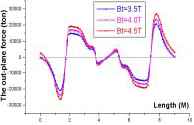
The result of the calculations in Fig 6 of [1] from the HT-7U team are shown in Graph 4 . See a detailed explanation in [1]. This values for Bt=3.5T are extracted from Fig 6 and shown in Graph 5 superposed to the ones in Graph 3. The MEMCEI values in Graph 5 are scaled and use the units ton * m.
The general structure of the loads from MEMECEI is very similar to the original Fig 6 of [1].
The total component Y of the momentum, My, on the coil is, in each calculation is:
A : 1.535 x 10⁶ N m = 156.5 ton * m
B : 1.543 x 10⁶ N m
C : 1.523 x 10⁶ N m
D : 1.580 x 10⁶ N m
These results are very similar, supporting the correction of the calculations.
However there is a very important discrepancy between this values and the result in [1], where the value is 288 ton * m. It is about twice as 156 ton * m, the same factor of deviation that appeared in [6].
More information about the exact magnetic field inside the conductor according to HT-7U is necessary to discover where is the mistaken point of the calculation.
Additionally Mx= 515 N m Mz= 163 N m for case D. They should be zero in an ideal tokamak but are small enough for the purpose here.
Calculation C resulted in a very similar profile of forces to A and D and in similar My. It seems that passing from 50 to 200 elements has little relevancy in this model.
Further developments
It is necessary to discover the reason of the discrepancy and allow the calculation of the profile of forces on the conductor in cases of the type B.
References
[1] "The Analysis and Calculation for the Toroidal Magnetic field of HT-7U" , Chen wenge(陈文革), Pan yannian(潘引年), Wu songtao(武松涛), Weng peide(翁佩德). Institute of Plasma Physics, Chinese Academy of Sciences.
[3] “Engineering of the HT-7U Superconducting Magnet Systems”, S.T. Wu, W.Y. Wu, et al, Institute of Plasma Physics, Chinese. A of. S.
[4] "Design of the Poloidal Field System and Plasma Equilibrium of HT-7U Tokamak" , Wu Weiyue and Li Baozeng, et al. , Institute of Plasma Physics, Chinese Academy of Sciences.
[5] "Stray magnetic field in HT-7U. Calculation using MEMCEI v2.1 finite element code" , Vicente M. Queral . See “Last results”
[6] "Magnetic field and forces calculation using MEMCEI v2.1 finite element code. Analysis of the convergence of the solutions" , Vicente M. Queral . See “Last results”
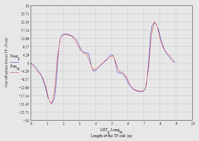
Graph 5 . Out-of-plane forces on the length of the TF coils using MEMCEI v2.1
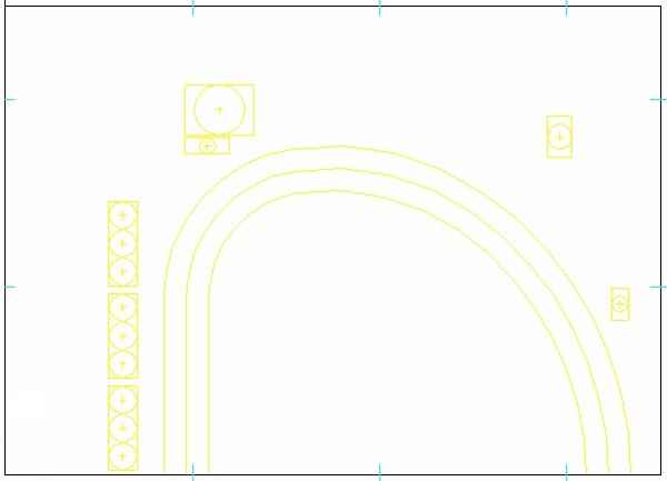
Graph 1 . Metallization of the PF coils in HT-7U to be used it in MEMCEI.
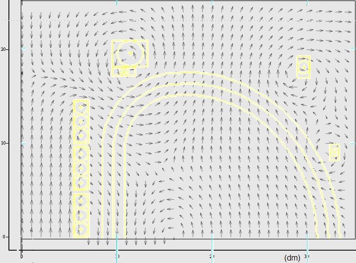
Graph 2 . Magnetic field in the plane x=0 . Quadrant X+ Y+ .
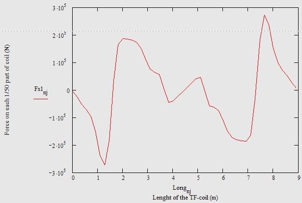
Graph 3 . Out-of-plane forces on the length of the TF coils using MEMCEI v2.1
Fx1 : Force in Newton on each 1/50 part of the length of the TF coil.
Long : Point on the TF coil where the force is applied. There are 50 points starting from the inboard equatorial plane.
Graph 4 , Out-of-plane loads on the TF coils as appear in [1], in ton * m
Graph 5 . Out-of-plane forces on the length of the TF coils using MEMCEI v2.1
Fxm : The same value Fx1 in ton*m and using a multiplicative factor of 0.781
Long : The same as in Graph 3
Fout : Values extracted from Fig 6 of [1]
Last Update 08-03-2005