An improved code MEMCEI v2.1 similar to version 2.0 (see "Last results") which allows the use of a higher number of elements, the use of wires with different currents, and a slight higher speed of processing has been used.
The objective is to analyse if the solution obtained using MEMCEI converge towards the HT-7U team results when more loops per coil are calculated. Three different modellizations of TF coils are used, establishing structures (see figures1-3) that are easy to interpret as a convergence issue.
Modellization
The general characteristics of this modellization is described in "Magnetic field and forces calculation using MEMCEI v2.0 finite element code. First results obtained" (See "Last results"). It uses cylindrical elements and the number of elements depend on the calculation A, B or C. The 130 turns per coil are reduced to 1, 5 and 13 modelled turns repectively.
Magnetic Field
The MEMCEI code v2.1 is being compared with the TF coils of the HT-7U tokamak, one of the most recent superconductor tokamaks. The TF magnetic field of this tokamak was calculated by the HT-7U team using the EFFI code. The same code was used in Wendelstein 7-X.
Data corresponding to the HT-7U geometrical inputs and results come from [1] [2] and [3]. The model in HT-7U is divided into 164 current elements, the current is 14,3077 kA to obtain 3.5 T at the plasma centre, having 130 turns each TF coil. The torus is composed of 16 TF coils.
A) Calculation A. Using MEMCEI v2.1 800 elements of current are calculated, distributed in 16 TF coils and using only loop of current per coil. This amounts up to 50 current elements each D shape loop. The results obtained using the most accurate HT-7U geometry available till now are expressed in graph 1.
B) Calculation B. Using MEMCEI v2.1 3680 elements of current are calculated, distributed in 16 TF coils and using 5 loops of current per coil. There are one loop of 50 elements and 4 loops composed of 45 elements. The results obtained are shown in graph 2.
C) Calculation C. Using MEMCEI v2.1 9440 elements of current are calculated, distributed in 16 TF coils and using 13 loops of current per TF coil. There are one loop of 50 elements and 12 loops composed of 45 elements. The results obtained are shown in graph 3.
The deviation between this calculations and the EFFI-HT-7U team calculations decrease when more elements are used. The increment of accuracy when passing from calculation B to C is less important than in the step from A to B, so it is supposed that more loops for each TF coil will not increase significantly the accuracy.
The reason for the remaining discrepancy in case C is not clear. In a simulation using 40000 spherical elements a similar result as graph 3 were obtained thus supporting the results in grap 3. However it is necessary a better knowledge about the modellization of the currents in the EFFI-HT-7U team and the exact dimensions of the TF coils to know what is the reason of the remaining deviation.
Further information, if available, will be request to the HT-7U team.
Forces
For the standard mode Bt=3.5T , the centering force on each coil is 989.3 ton [2] , and from MEMCEI 2.1 using 13 loops for each TF coil, the centering force on one of the TF coils that is in the plane YZ (z is the vertical axis of the torus) has resulted :
Ftot,x = 3,507 x 10 -8 N
Ftot,y = -9,656 x 10 6 N
Ftot,z = -114,918 N
Ftot,y = -984,3 ton
The deviation is 0,5% in relation to the value calculated by the HT-7U team using EFFI code. This is acceptable for the present objective of MEMCEI code.
The relatively high value of Ftot,z that should be zero ocurred due to an asymmetry in the position of the finite elements in relation to the equatorial plane of the tokamak, asymmetry that was realized when trying to explain this anomaly.
Further developments
An interface between the magnetic field calculations and mechanical stress using the French Code_Aster is planned to be developed so to improve in some kind of evolutionary way the whole system, including magnetic, electrical and mechanical specifications.
[1] “Engineering of the HT-7U Superconducting Magnet Systems”, S.T. Wu, et al, Institute of Plasma Physics, Chinese Academy of Sciences.
[2] “The Analysis and Calculation for the Toroidal Magnetic field of HT-7U”, Chen Wenge, et al, Institute of Plasma Physics, C. A. S.
[3] “Design of the HT-7U Tokamak Device”, S.T. Wu, et al, Institute of Plasma Physics, C. A. S.
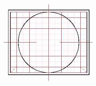
Fig1. One loop each TF coil. Calculation A
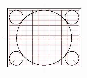
Fig 2. Five loops each TF coil. Calculation B
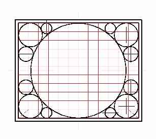
Fig 3. 13 loops each TF coil. Calculation C
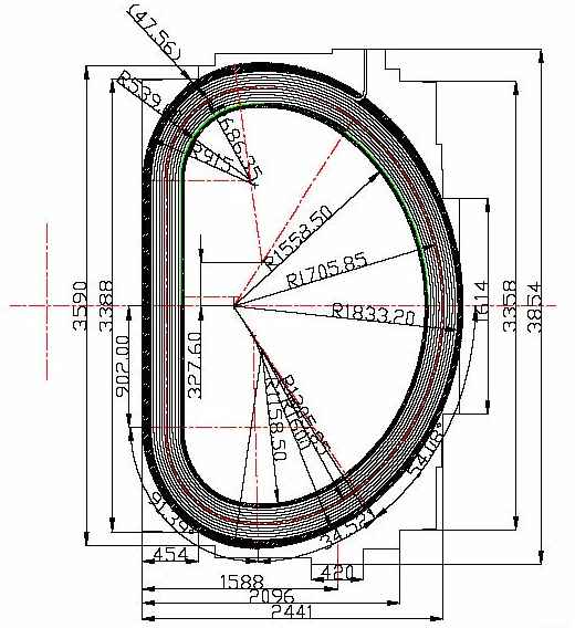
View of the TF coil HT-7U
as shown in [2]
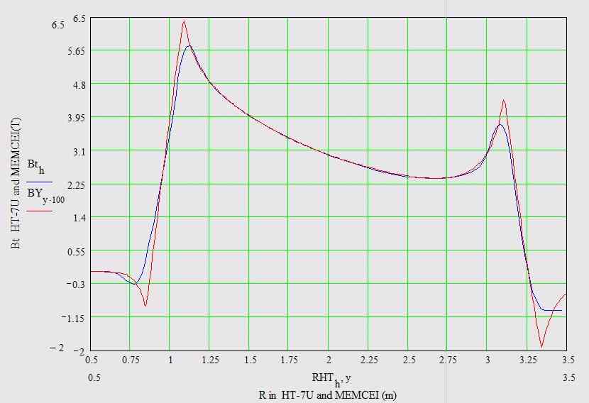
Graph 1 , Calculation A : HT-7U Bt calculations using EFFI and MEMCEI codes.
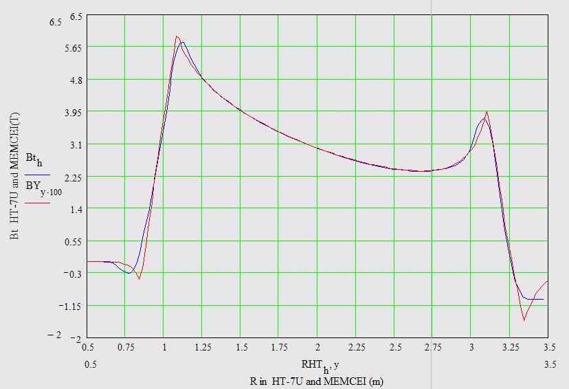
Graph 2 , Calculation B : HT-7U Bt calculations using EFFI and MEMCEI codes.
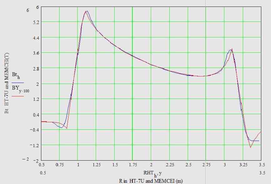
Graph 3 , Calculation C : HT-7U Bt calculations using EFFI and MEMCEI codes.
For graph 1-2-3 :
- Bth is the magnetic field in the toroidal axis using EFFI,
- BYy100 is the toroidal magnetic field at the Y axis using MEMCEI v2.1
- RHTh is the radius of the HT-7U tokamak, data from graph in [2]
- y is the radius of HT-7U for MEMCEI
Last Update 06-02-2005