Abstract : Continuing with the test of the MEMCEI v2.1 code, the recalculation of the forces and momentum on the TF coils in HT-7U tokamak is carried out. The profile of the forces along the length of the coil is obtained and so the overturning momentum. It is compared with one report from the HT-7U team.
Modelling
The system is modelled like shown in [5]. Since only the report [1] contains the PF currents and the resultant momentum on TF coils for specific calculations, it is used as an example. Unfortunately this report is quite old (1999) and it seems that some changes in the HT-7U geometrical design has taken place. However it is useful as a first try. This design will be denoted here as OLD design. The more recent design (not the last really) will be denoted as NEW and is described in [3] and [4]
In the OLD design the PF9 and PF7 was defined as an single vertical bigger PF7 coil. In this calculation the PF7 coil has n7= 11 * 4 turns , n9 = 14 * 20 - n7 turns (PF7 of the OLD design had 14 * 20 turns), n11= 7 * 10 turns. The other coils have the same number of turns in both designs. Additionally there are slight differences in the position of the coils between the two designs that are considered irrelevant here. This information is detailed on Table2, Fig2 and Fig3 in [2]. All those transformations are done to try not to redesign the NEW geometrical model of the HT-7U to produce the OLD design of HT-7U.
Two calculations are done, calculation A and B. The A uses only one loop per TF coil while the B uses 5 loops and 230 elements per TF coil. See [5] to know the different types of models of TF coils. This can be useful to know if the less accurate result converge to a better result.
Magnetic Field
The currents are taken from Table 6 of [1] . These currents correspond to a final stage in a normal pulse. 106 A is used for plasma current. TF coils are loaded with 12200A , using 196 turns. These are the conditions for Bt=4.5T in the OLD design.
The resulting magnetic field in the plane x=0 . appears on the Graph 1. Here the use of PF7+PF9 as a single PF7-OLD coil was not implemented yet.
Forces and momentum
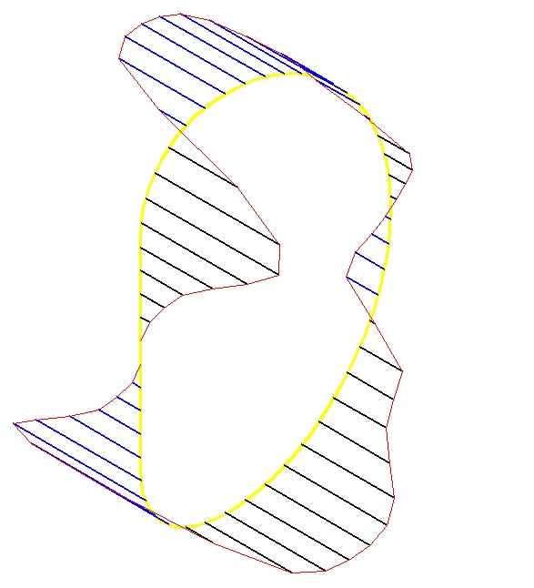
From this magnetic field the forces and momentum are calculated. The forces from calculation A are shown on Graph 2. The maximum force is 2.386 x 10⁶ N . Presently individual forces acting on particular segments of the coil cannot be calculated using MEMCEI v2.1 code for the case B.
The general structure of the loads is very similar to the original figure from Table 6, figure 7 of [1], copied in Graph 3. Since small variations on the current of the PF coils produce notable modifications in the structure of the resulting forces, the correctness of the code is positively supported.
The respective moment on the TF coil at axis Y- (this is the TF coil number 1), in calculation A, is My= 2.019 x 10⁶ N m = 205.8 ton m. From [1] the result is 398 ton m . The reason for the enormous discrepancy is not clear till now. One value is approximately twice the other but this does not help. Further information about the magnetic field calculated in HT-7U is necessary to know at what point the calculation is mistaken.
Additionally Mx= 8318 N m Mz= 52 N m . They should be zero in an ideal tokamak but are small enough.
In calculation B My= 2.027 x 10⁶ N m so in this case the influence of the number of elements of the TF model have little impact.
Further developments
It is necessary to discover the reason of the discrepancy.
References
[1] "The Design Parameters for HT-7U TF System" , Wu Weiyue, 9-6-1999 ,
[2] "Design of the Magnetic Field for HT-7U Tokamak", Wu Weiyue, Guo Zengji, Du Shijun'. Institute of Plasma Physics, Chinese Academy of Sciences , 'Hefei University of Technology
[3] “Engineering of the HT-7U Superconducting Magnet Systems”, S.T. Wu, W.Y. Wu, et al, Institute of Plasma Physics, Chinese. A of. S.
[4] "Design of the Poloidal Field System and Plasma Equilibrium of HT-7U Tokamak" , Wu Weiyue and Li Baozeng, et al. , Institute of Plasma Physics, Chinese Academy of Sciences.
[5] "Stray magnetic field in HT-7U. Calculation using MEMCEI v2.1 finite element code" , Vicente M. Queral . See “Last results”
[6] "Magnetic field and forces calculation using MEMCEI v2.1 finite element code. Analysis of the convergence of the solutions" , Vicente M. Queral . See “Last results”
. Out-of-plane force on the TF coils from MEMCEI
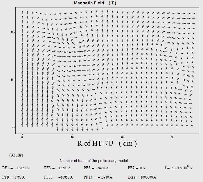
Graph 1 . Magnetic field in the plane x=0 . Quadrant X+ Y+ .
Graph 2 . Out-of-plane forces on the TF coils from MEMCEI
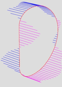
Graph 3 , Out-of-plane forces on the TF coils as appear in [1]
Last Update 11-02-2005