Abstract : Details about the conditions and gradual improvements in the pulses in UST_1 are reported. The results, deficiencies or absence of the expected outcomes from each pulse is summarized.
List of pulses and main parameters
t = pulse length in seconds
B= approximate value of the magnetic field at axis
It = Ampere-turns in each coil
P = Pressure in the vacuum vessel in Pa
G.V. : grid voltage for acceleration of electrons in e-beam
Is = current of electrons in e-beam source (not the electrons in the beam which are unknown)
Fil. Volt = voltage at the tungsten filament
| # | Date | t | B | It | P | G.V. | Is | Fil. Volt | Result |
| s | mT | A-turn | Pa | V | mA | V | |||
| 1 | 23-5 | 1.1 | 8 | 490 | 0.05 | 24 | 0.043 | 7.94 | Too much background light. Tilted e-beam. Visual inspection of the image |
| 2 | 23-5 | 1.1 | 8 | 490 | 0.05 | 24 | 0.13 | 9.99 | same as #1 |
| 3 | 23-5 | 1.1 | 8 | 490 | 0.05 | 31.4 | 0.17 | 9.99 | same as #1 |
| 4-6 | 25-5 | 1.1 | 8 | 490 | 0.05 | 31.4 | - | 9.99 | PC controlled pulses Background. CCD camera |
| 8 | 27-5 | 2.0 | 8 | 490 | 0.07 | 46.6 | 0.26 | 11.2 | |
| 10 | 27-5 | 2.5 | 8 | 490 | 0.07 | 58.1 | 0.30 | 11.2 | ~Max Fil Volt Background. Low resol. |
| 11 | 29-5 | 2.5 | 8 | 490 | 0.1 | 112 | 11.1 | 11.2 | Visual inspection. No result |
| 13-15 | 29-5 | 2.5 | 8 | 490 | 0.1 | 112 | 11.1 | 11.2 | New e-beam. Higher G.V. |
| 17-19 | 8-6 | 4 | ~8 | - | 0.04 | 138 | ~14 | 11.5 | First ray |
| 20-22 | 8-6 | 4 | ~8 | - | 0.04 | 138 | 11.5 | visual inspection | |
| 24 | 8-6 | ~8 | - | 0.04 | 63.8 | - | 11.5 | vissible ray | |
| 25 | 8-6 | ~8 | - | 0.04 | 29.3 | 2.85 | 11.5 | faint ray | |
| 26 | 8-6 | ~8 | - | 0.04 | 148 | 38 | 11.5 | worse ray | |
| 27 | 8-6 | ~8 | - | 0.04 | 158 | 99 | 11.5 | a soldering melted | |
| 28-32 | 10-6 | 2 | 13.6 | 836 | Increasing B | ||||
| 34 | 11-6 | 2 | ~14 | - | 0.05 | 34 | 11.6 | Beam turns. (By sight) | |
| 35 | 11-6 | 2 | ~14 | - | 0.05 | 34 | 11.6 | Glitter on the rod. (By sight) | |
| 36 | 11-6 | 2 | ~14 | - | 0.05 | 34 | 11.6 | Fluorescent point recorded | |
| 37 | 11-6 | 2 | ~14 | - | 0.05 | 34 | 11.6 | Optic filter installed | |
| 38 | 11-6 | 2 | ~14 | - | 0.05 | 34 | 11.6 | Perhaps 2 points | |
| 39 | 11-6 | 2 | ~14 | - | 0.05 | 34 | 11.6 | One point | |
| 40-44 | 29-6 | 2 | ~14 | 0.05 | 34 | 11.6 | Argon + helium gas | ||
| 45-48 | 6-7 | 2 | ~14 | 0.05 | 70 | 11.6 | Helium gas | ||
Results and improvements
Pulses #45 to #48
Conditions of the experiences:
* These pulses are run mainly to know if the e-beam can be used for leak testing at high vacuum.
* The condions are the same as in pulses #40 to #44 but the acceleration voltage of the e-beam is now 70V.
Results :
- No visual result was observed on the e-beam, it remained blue. A low cost RGA was searched in ebay. At the moment an AMETEK Dycor Quadlink system from ebay is being shipped. The cost is 80€ !! + 140€ shippment from Singapur. However the unit will be probably out of order, only one free code for this RGA has been found and it needs to arrive here -not easy issues.
Pulses #40 to #44
Conditions of the experiences:
* The heater of the diffusion pump was repaired and a customised one is built as spare part. (no low cost commercial heaters for this old pump)
* These pulses are run mainly to know if the e-beam can be used for leak testing at high vacuum. Some glow discharges were done with Argon and air but it is only useful in the range higher than ~10Pa.
* The conditions are the same as in pulse #39.
* A considerable leak of 2.9 x 10⁻³ Pa m3/s is created in one port by using a calibrated hair. Different pressure on the NW40 vacuum clamp gives different leaks.
* Argon gas is introduced around the "leak" to observe the effect. Acetone was also used.
* The pressure during the experience was always higher than 0.1 Pa due to the controled leak.
Results :
- No visual result was observed on the e-beam. The beam remained blue in all the experiences even with the use of acetone at pressures higher than 1Pa. In this case clearly the partial pressure of the acetone is almost the total presure. Perhaps the visible spectrum changed but the spectrometre is not installed and by now it lacks of photodectector.
- The tungsten filament of the e-beam did not melt. The filament was under pressures higher than 1Pa for about 10 seconds.
Pulses #34 to #39
Conditions of the experiences:
* The e-beam is located at the magnetic axis.
* Two batteries are used, about 14mT.
* The pulse length is reduced to allow more pulses in an experimental sesion.
* 30 frames/s are taken after the pulse #35.
* A dielectric interference band-pass filter of good quality is installed. This filter is centerd in 500nm, Full Width=50nm. It was the most similar filter in ebay for the gaussian-like emission curve of P24 phosphor.
Results :
The blue-violet e-beam was seen by sight rotating at least 3/4 of turn. However only in the next pulse a very brief sparkle was seen on the rod. The rod moves and only one or two turns can be seen due to the low vacuum.
The poloidal projection was recorded the first time in the next pulse. Immediately the filter was installed and the background was notably diminished.
It seems that two points are recorded in pulse #38. If true the e-beam has rotated 2 toroidal turns, see photo 5. The future plasma will reach only 2eV and max 5eV so 34eV of the present e-beam is a high value for this small stellarator.
Necessary improvements
* The e-beam will be moved to obtain a bigger surface and simultaneously to avoid a possible collision of the e-beam with the back of the e-gun. The movement must be moderate because the ray can escape if B is weak.
* The energy of the e-beam will be reduced. However it must allow detection.
* The leak need to be found and sealed. This is not a trivial issue. A He leak detection system is not available and the leak is probably under the plaster or even under one coil. The change in the colour of the e-beam when an exotic gas is introduced through the leak is planned as a way to find the leak. Acetone cannot be used here due to the danger of explosion of the plaster chamber filled with acetone.
* The camera will be better fixed and two small black points will be marked on the fluorescent rod to have a reference.
Pulses #28 to #32
Conditions of the experiences:
Simulations
* Some simulations with drifts-ON are carried out using SimPIMF to detect why the ray escapes. As supposed in pulses #17 to #27, the magnetic field was so weak that any reasonably energetic (to be detected) e-beam escaped. In the simulation with ideal and even in real-like deformed coils the electrons escaped after one turn for 68eV. So the influence of the low quality provisional coils was less significative than the strength of the magnetic field B.
* An additional battery is installed (total 2 batteries). The definitive coils with 6 turns will need at least 6 batteries and so the provisional coils.
Results :
~834A-turn is obtained, very similar to the calculation. 4100A-turn will be needed in the future to obtain adequate B.
Necessary improvements
- More batteries will be installed for the definitive coils. The impedance will match poorly if 3 batteries are used with the present provisional coils
Pulses #17 to #27
Conditions of the experiences:
* A new e-bean has been built. Improvements :
- The filament is smaller (10W) and is nearer to the anode (~1mm). The size of the hole is 1.25mm.
- The light bulb is totally inside a copper tube.
- A brass-glass base supports the bulb.
- An adjustable support for the e-beam is designed.
- The surfaces inside the tube are painted with adequate black paint and baked at about 200ºC. This might remove 80% of the background light.
- The tube, frontal cap and base are soldered and/or light tight.
- A new feedthrough is assembled. It is formed by o-rings and screws (it does not leak).
* The e-beam is injected form the theoretical magnetic axis. In the last experiences it was thrown from a point near the last closed magnetic surface but the ray was not observed.
This location is more adequate to see the ray at first.
Results :
The e-beam, turning around the torus, was finally observed. A thin violet ray was visually observed and filmed very weak, see Photo 4 and 3. However the ray collides with the wall after about 135º toroidal angle of rotation and does not reach the fluorescent rod. The reasons could be: a) The provisional coils are too inaccurate. b) The e-beam is not located at the correct point. By now it cannot be moved from the exterior of the stellarator. c) The beam is excesively energetic or/and the magnetic field is too weak yet. d) The calculations and simulations of coils and magnetic fields are incorrect. e) The grooves are not manufactured as designed due to some mistake (less probable).
Necessary improvements
- A simulation of the beam with drifts, with the real energy (~100eV) and taking the theoretical or the approximate real coils, should be carried out.
- The e-beam position will be varied towards the direction indicated by the simulations.
- Optical filters in the range of the N2 emission will be ordered.
- A more sensitive camera should be installed in spite of the far higher cost. Alternatively a digital photographic camera or a traditional camera equipped with asensitive film might be used.
Pulses #13 to #15
Conditions of the experiences:
* The e-bean has been improved. The acceleration grid is flat. Bigger hole (~2mm). Better closed but more light escapes through the hole.
* Acceleration voltage can reach 250V DC with the new power supply.
* A 12mm objective for the camera is installed.
* ' Is ' has a reasonable value, 11mA. Only a small fraction of the total, very roughly 5 - 10% will escape as a beam, 0.5mA, enough to produce fluorescence. Added on 8-06-2006 : Perhaps the current was not correctely observed but it was not seen later. In any case the e-beam was of excessive low quality.
Necessary improvements
- Optical filters in the range 490 - 530nm are being shipped.
- The hole will be reduced to 1 or 1.25mm diameter.
- The oscillating fluorescent rod might not be at ground potential (only a contact point).
- Perhaps the provisional coils are excessively inaccurate and the beam escapes; the e-beam will be located at the magnetic axis to decrease difficulties.
- The fluorescent rod will be tested with ultraviolet light.
Pulse #10
Conditions of the experiences:
* The pulses are rutinely run automatically.
* Pulses are longer now, 2.5s, with no execesive heating of the coils.
* The voltage at the filament migt reach 12V (halogen bulb). However the gas in the halogen bulb protects the filament, so some safety margin is necessary.
Necessary improvements
Additionally to the remaining issues, the e-beam will be modified to try to reach 2mA.
Pulses #4 to #6
Conditions of the experiences:
* A PC controled system was installed. It generates predefined pulses. In this case 1.1 seconds of power for TF modular coils and a square wave (0.3s ON 0.3s OFF) for the acceleration grid.
* The firewire camera, the card and a new (really an old second hand) PC is installed. The free VirtualDub code to process video images is working.
Necessary improvements
The background is very intense, see Photo 1. Waiting for the ceramic cover for the e-beam. Soon the definitive objective for the camera (more precision). Higher power in the e-beam.
Pulses #1 to #3
These are the first pulses to test different elements.
Conditions of the experiences:
* The coils are provisional and of low quality so the magnetic surfaces will be deformed if any.
* A small leak (no outgassing) seems to deteriorate the ultimate pressure that was obtained without vacuum vessel. This was already found after the mechanisation of the coils. Possible but not easy to solve.
* A weak general fluorescence was observed, but no signal of the e-beam. Perhaps it is too weak or collides with the first wall. The pressure seems low enough to obtain a mean free path to reach the fluorescent oscillating rod.
Necessary improvements
- It is necessary to install the PC control system to switch the main power, the filament (to lengthen the life) and the pulses of the acceleration grid (to separate background). The manual operation is almost impossible, innacurate and unsafe even using only several switches.
- It is necessary to install the CCD camera to record the smallest fluorescence of the rod and filter and compare background with e-beam fluorescence.
- Gradually the voltages will be increased and so the power.
References
None
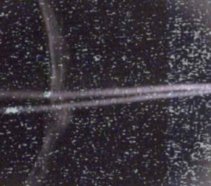
Photo 5 . Pulse #38. Two points of the magnetic surface are obtained on the fluorescent rod. The image is the addition of two filtered images.
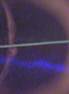
Photo 4 . Pulse #34. Treated image of Photo 3 . The background is subtracted and the result is treated : contrast-brightness , filtered , diffused. Finally the result is added to Photo 3 to recognise the position of the e-beam. The camera should be more sensitive because the ray is clearly seen by sight through the viewport. Date 08-06-06
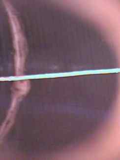
Photo 3 . Original image from the CCD video camera. The e-beam is blue-violet (Nitrogen emission at 430nm) and it is captured very weak due to the low sensitivity of the camera. (The horizontal white line is the fluorescent rod). Date 08-06-06
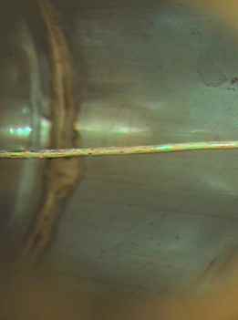
Photo 2 . Pulse 13 . A good quality video of the fluorescent rod. Date 29-05-06
[Photos of very low quality removed due to web memory limitations]
Photo 1 . First video (here two photos) of the inside of the torus and the fluorescent rod. Low quality by now. High background and little or no fluorescence. The photos belong to the instant t=0.26s and t=1.04s . The rod oscillates freely with low friction after an initial magnetic impulse. The magnet is removed after the pulse, the small ferromagnetic piece is outside the main magnetic field so the influence is minimal. Date 25-05-06
Figure 1 . Field line mapping experimental setup. The flexible coupling has been changed into an oscilating rod.
Date of publication 23-05-2006. Continuous updating