Abstract : The vacuum system for the UST_1 torus and the present status of the assembling of the vacuum system is described. UST_1 stands for “Ultra small torus”, an educational torus that is being built in Castellon, Spain [1] [2] [3].
Objective
Built an operative vacuum system to experiment with vacuum technologies and advance towards the development of an operative vacuum system for a small stellarator or tokamak. The speed and ultimate pressure reached with this vacuum system depends on the quality and cost of the equipment. In this first stage the aim is to reach 10-2 Pa, far from the requirements for an operative torus, for example 10-6 Pa in Wendelstein 7-X.
Experimental system
The central elements of the system are the roughing pump and the high vacuum pump.
Due to the high cost of the turbomolecular pumps, even surplus or ebay products, a diffusion pumps is chosen as the high vacuum pump.
The roughing pump will be an oil-sealed rotary
vane vacuum pump.
Additionally the necessary flanges and valves are planned.
According to the limitation of funds and the
surplus equipment available, the vacuum system has been reduced to the
minimal expression. The roughing line is eliminated and the number of vacuum
gauges are less than optimum. The common UHV gate valve at the foreline of
the diffusion pump is replaced with an angle bellows vacuum valve, equipped
with KF40 flanges.
Some elements will be added when they were found at low cost.
The layout is displayed in Graph 1.
Present status of the vacuum system
Some of the elements have been receipt while
others are shipping at this moment.
The diffusion pump, a LEYBOLD from an electron microscope has been
received and rebuilt.
Part of the fittings have already been silver soldered.
Two new thermocouple gauges, model KJL-1518 from Lesker company,
and additionally the interface for the A/D card are assembled and ready for
use.
Diffusion pump oil, type DC-704 from Lesker is stored.
One new Varian angle bellows UHV vacuum valve, electrically
operated, bellows and clamps are being shipped.
On the other hand a low cost mechanical pump is not available yet.
At the beginning a loaned air conditioned pump will be used.
The system from the ball valve to the vacuum chamber has been leak
tested.
In this experiment the vacuum chamber is only a closed mockup port,
acting the pipes and the diffusion pump as the vacuum volume. Leaks were of the order 2 to 4 x 10⁻³ Pa/m3s,
in the first test, high value
that was corrected. Leaks are 3.7 x 10⁻⁵ Pa/m3s
in the second test, after some improvements in tightness. This value is
passable for a volume of about 0.003 m3 becuase initial
calculations show that outgassing from a clean ceramic (steatite) vacuum
vessel or vapour pressure from oils or dirts in the pipes have a virtual
throughput higher to 3.7 x 10⁻⁵ , so at this point difficulties
concentrate in cleanliness.
In another test the total leak rate from the ball valve up to the top of the
diffusion pump were relatively low, around 1.7 to 1.9 x 10⁻⁵ Pa/m3
. This experimental assemble is shown in Photo 1.
Further developments
The vacuum system needs to be totally assembled and stated.
References
[1] "Forces on HF coil of the first outline of the UST_I" . Vicente M. Queral. See "All past research" in this web.
[2] "FE stress analysis for a first outline of the vacuum vessel of UST_1" , Vicente M. Queral. See "All past research" in this web.
[3] "1200A test Pulse and set-up of Data Acquisition" Vicente M. Queral. See "All past research" in this web.
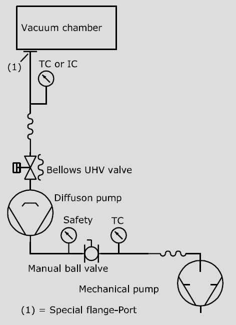
Graph 1. Vacuum layout of the experiment
Graph 1. Vacuum layout of the experiment
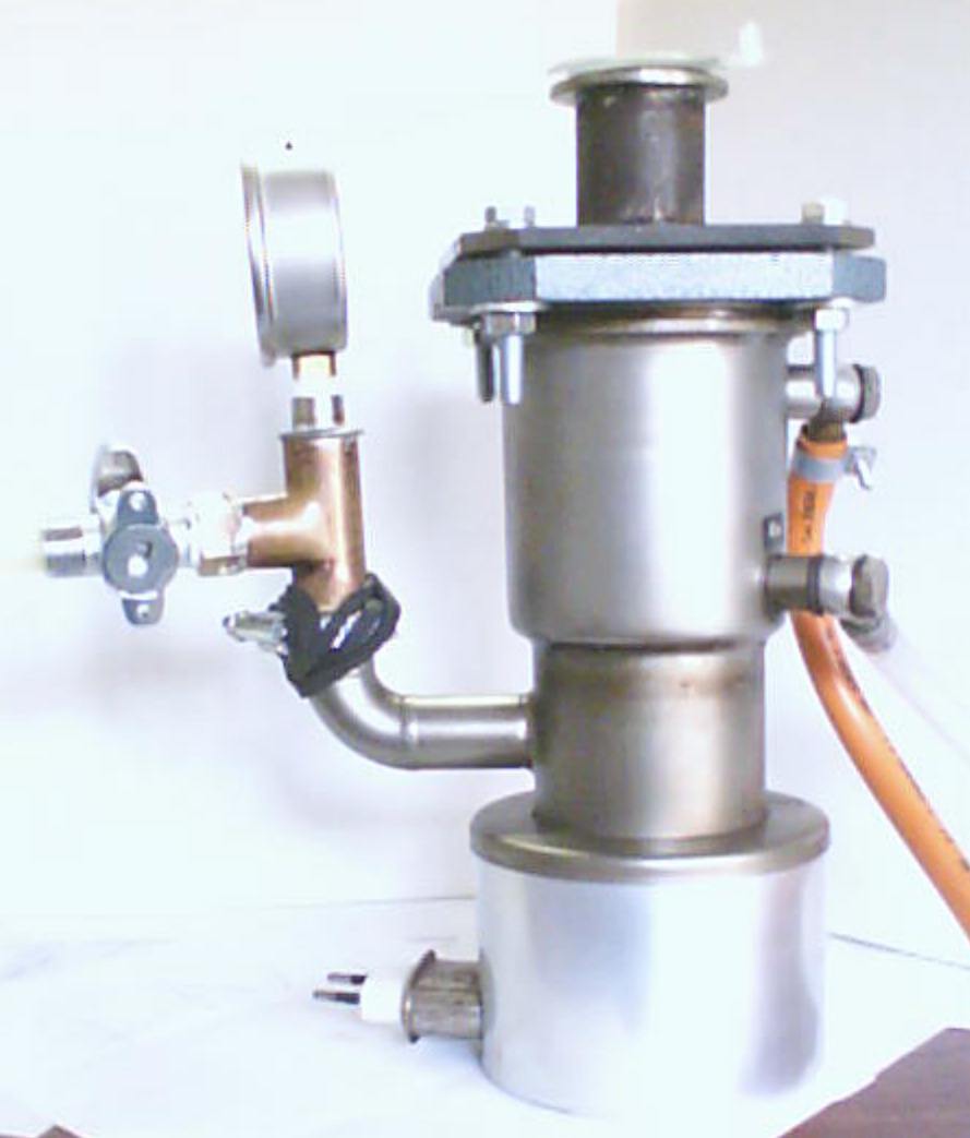
Photo 1. Diffusion pump and some fittings..
Last Update 12-09-2005